There will be a test on some of the topics covered during our course on the date above.
It will be a written test but you can refer to anything on the Internet and will need to be able to write and run programs in the Arduino environment. Please bring your Arduinos to the test and also bring a LDR, light dependent resistor as you will be asked to write a program that will involve analogue input.
There will be a question about the front page of the Atmel pdf for the AVR328. You should be able to explain most of the features mentioned there.
There will be a question about different embedded buses and their main features.
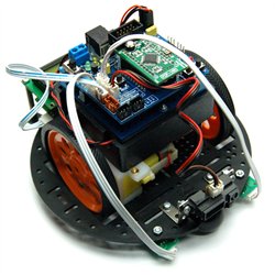
You will be asked to write a schematic for a robotic circuit.
There will be other questions on work covered in class.
There will be a revision class the day before so bring any questions along to that.
Thursday, November 10, 2011
Sunday, November 6, 2011
Toggling a LED
This is a better way of getting the classic LED toggling Blink program to turn the LED to to alternate state. I'd seen this elsewhere but forgot about it.It was recently suggested by David Beath, a student in our class.
boolean ledState = 0; //in the setup
digitalWrite(13,(ledState = !ledState)); // in the loop
boolean ledState = 0; //in the setup
digitalWrite(13,(ledState = !ledState)); // in the loop
Tuesday, November 1, 2011
PROGMEM example
#include <avr/pgmspace.h>
 char buffer [5];
 word serialCount;
void setup(void)
{
    Serial.begin(38400);
    Serial.println("\nPress space bar .");
//    while (Serial.read() != 32)   delay(1); // Wait for space

}
const int mydata[10][10] PROGMEM = {
    '0', '1', '2', '3', '4', '5', '6', '7', '8', 'A',
    '1', '1', '2', '3', '4', '5', '6', '7', '8', 'B',
    '2', '1', '2', '3', '4', '5', '6', '7', '8', 'C',
    '3', '1', '2', '3', '4', '5', '6', '7', '8', 'D',
    '4', '1', '2', '3', '4', '5', '6', '7', '8', 'E',
    '5', '1', '2', '3', '4', '5', '6', '7', '8', 'F',
    '6', '1', '2', '3', '4', '5', '6', '7', '8', 'G',
    '7', '1', '2', '3', '4', '5', '6', '7', '8', 'H',
    '8', '1', '2', '3', '4', '5', '6', '7', '8', 'I',
    '9', '1', '2', '3', '4', '5', '6', '7', '8', 'Z' };

void loop(void) {
    int i,j;
    byte n;
    Serial.println("\nData by Rows.");
    for (i=0; i < 100;i++) {
  // Serial.println(" ");
        if ((i %8)==0) Serial.print("|");
        if ((i %16)==0) Serial.println("");
   n = pgm_read_byte_near(i);
 // Serial.print(n, HEX);
          Serial.print(" ");
          sprintf(buffer, "%02x", n);
          Serial.print(buffer);
          serialCount++;

         // Serial.print("\t");
     }

    Serial.println(" ");
    Serial.println("\nData by Columns.");
    for (i=0; i < 10; i++) {
   Serial.println(" ");
   for (j=0; j < 10; j++) {
  n = pgm_read_word_near(&mydata[j][i]);
  Serial.print(n, BYTE);
   }
    }
    Serial.println(" ");    setup();    Serial.println(" ");  //start over
}
Tuesday, October 25, 2011
Timer0 First Program- Polling
/*
  Timer 0 Experiment
 */
int state = 1;
byte ticks, tocks;
long loopCounter;
long popCounter;
unsigned long time;
void setup() {
  // initialize the digital pin as an output.
  // Pin 13 has an LED connected on most Arduino boards:
  pinMode(13, OUTPUT);
  TIMSK0 = 0;     //turn off Interrupt for Timer0
  TCCR0B = 5; //Prescaler divieds by 1024
  Serial.begin(9600);
}

void loop() {

   while(byte(TIFR0 &0x01) ==0){}; // loop til flag goes up
    TIFR0 = 1;      //clear flag
    ticks++;

    if (ticks == 60) {
      ticks=0;
      ToggleLED();
  //    Serial.print("TT ");
    }
}
void ToggleLED(){
  if (state==1) {
    digitalWrite(13,LOW);
    state = 0;
  }
  else {
    digitalWrite(13,HIGH);
    state=1;
 //   Serial.print("I've tohggled");
  }
}
Sunday, September 18, 2011
IIC or I2C or TWI
 |
| The TWI bus |
Good tutorial from DigiKey
other training modules of electronic parts from digikey
A good introduction to IIC with an Arduino Focus is here.
The Arduino library with functions that handle the TWI bus is the Wire Library
A good example of using IIC eeproms with Arduinos is here.
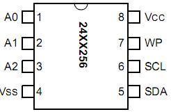
A typical IIC device is the eeprom below.
An Arduino setup
and you can join up two Arduinos using the IIC bus
This code worked for me straight from the forum to the freetronics eleven at 24LC256.
And here's the data on the24LC256 eeprom.
Tuesday, September 13, 2011
Tuesday, August 30, 2011
Accelerometers
How do we sense movement and store and display it? Study this IC and come up with a schematic and software to read and display outputs. See the associated task.
Tuesday, August 23, 2011
Pin outs
We found that the pins on the Arduino board did not correspond to the pins on the AVR Mega328. Here's a useful mapping of pins. Note the two hardware interrupt pins.
Interrupts
There are two hardware interrupt pins on our Arduino. Interrupt 0 and interrupt 1. These cut off what ever processing is going on and carry out the interrupt service routine that you indicate.
Tuesday, July 26, 2011
Tasks
Tasks
Please respond to these tasks in your blog using the same reference numbers.
Please respond to these tasks in your blog using the same reference numbers.
- Find two Arduino based robot YouTube videos that appeal to you. Put the links into your blog and be prepared to share the videos with the rest of the class.
- Find a diagram of our Arduino board or similar and indicate with arrows where the Tx and Rx pins are on the Arduino I/O pins as well as on the microprocessor itself.
- Write a program to display the ascii table in the serial monitor. Publish a screen shot in your blog.
- Wind up the baud rate in program 4 and report how fast you could get it.
- Write a program to take a key press and output the key and its codes in binary, decimal in hex.
- Repeat 5 but this time use another serial monitor, perhaps Bray++. Screen shot required.
- Connect up your RS232 Tx to the Rx of another Arduino. Output an "A" every second so that the input screen of the other Arduino writes this when it checks and prints the input serial screen. Take a photo of your set-up and publish it in your blog along with the code for Rx and Tx Arduinos. Reverse your roles with your colleague's Arduino. That is, swap the Rx/Tx duties.
- Wrie a function called Hello() to output "Hello, world." when it's invoked. Call this function 10 times in your main loop().
- Write a function DoubleInt to double an integer. Call it like this: Serial.println(DoubleInt(myInt)). Call it twice; once with a number and once with a variable.
- Write a function to add B0111 to a byte passed to it. Call it 256 times in loop() using 0-255 as the parameters.
- Write a function to AND a byte with B01 and output the result to the screen. Test this in the main loop().
- Write a function to say "yes" if the LSB (least significant bit) is a 1 or "no" otherwise. Test in the main loop.
- Write a function to left shift a byte in the parameter postion two places to the left then output the original and the final byte.
- Write a program to output the bits, one by one, to the serial monitor screen from an arbitrary byte.
- Write a subroutine to output a byte using the RS232 soft-serial protocol using 8,N,2 at 9600.
- Input bytes into a colleague's Arduino using the soft-serial from your pin to the Rx of your colleague's Arduino. Write up your code and take a photo of the set-up.
- Write a soft-serial input, Rx, subroutine that takes bytes from a normal 5v RS232 Tx output at 8,N,2 at 9600.
- Get your new motor mini-board to spin in one direction.
- Get it to spin in both directions.
- Get it, using PWM, to spin at different rates.
- Output, using the photo-interrupter, the number of revolutions per second, your motor spins at.
- Same as 21 but this time using the PWM to raise and lower the speed that is reported on the screen.
- Same as 22 but this time add a comment with each speed output to indicate which direction it is spinning.
- Use the example given in class to write your own two wire protocol that can deliver 8 bits on the data line and use the clock line to indicate valid data. Test with a colleague's Arduino and write up your results.
- Same as 24 but this time use a four-bit data path.
- Plan a TWI between two Arduinos. Scan a diagram, or illustrate in some other way, how the connections will be set up and which is master and which is slave. Have a look at http://absences.sofianaudry.com/en/node/10 or at http://arduino.cc/en/Tutorial/MasterWriter for some example code.
- List the main functions of the Wire library. Say what they do with examples.
- Construct a real TWI between two Arduinos. Take a photo and publish your code and any issues you had.
- If I had three Arduinos, is it possible to produce an RS232 ring so that packets of information could go from any Arduino to any other?
- Write a paragraph about the two hardware interrupts on the Arduino and how to use them.
- Carry out the interrupt experiment from the Interrupt post. Change the code you find here.
- Find the post on the Triple Axis Accelerometer. This is an example of a sensor we have to deal with. Find out more information about this sensor and compose a schematic illustrating how you would use an Arduino to real acceleration in three dimensions and display the outputs. Your blog output should contain a schematic and code.
- Find a pin-out of the XbeePro. Using just Arduino's Tx, Rx ,Gnd and 3.3 VCC draw a quick schematic of how two Arduinos would talk to each other without wires.
- Use the above two tasks to produce a schematic of a circuit that would read the accelerometer 's three axis readings and then output to an Arduino and then broadcast out to another Arduino that would send the data to a serial terminal for saving in a file.
- Write the Arduino code for the sender that reads the accelerometer values and sends them via the XbeePro.
- Write the Arduino code for the receiver that's attached to the PC.
- Integrate the new eeprom library from the link here. You should be able to #include this new library this.
- You were issued with an eeprom 24LC64 IC. This is a TWI memory that you connect to SCL and SDA on the Arduino. Run the program from the blog. Show your code changes and the serial monitor output in your blog.
- The problem with the program above is that it can only handle about 30 bytes at a time. Overcome this problem so that any amount of data can be sent up to the capacity of the chip. Write up your findings.
- Copy the Timer0 Polling routine given to you in a previous post and run it with some tidying up. Show your tidy code.
- Repeat the program in 40 but this time make it work a one second LED flash using an interrupt service routine.
RS232
Communication
All intelligent mechanisms need a way of sending and receiving data. An old standard, still used is the RS232 serial standard.
A good site for RS232 information
All intelligent mechanisms need a way of sending and receiving data. An old standard, still used is the RS232 serial standard.
A good site for RS232 information
Subscribe to:
Comments (Atom)


